
AWS Certified Solutions Architect Professional – Study Guide – Domain 4.0: Network Design for a complex large scale deployment (10%)

4.1 Demonstrate ability to design and implement networking features of AWS
- VPC is a Virtual Private Cloud. You can have up to 5 on an AWS account, if you need more you can raise a ticket
- Create a VPC you need a CIDR block, a name tag and tenancy type of default or dedicated. Dedicated costs money, default doesn’t
- Creating a VPC automatically creates a routing table
- Subnets map to AZs on a one to one basis
- Amazon reserve five IP addresses on a subnet
- One Internet Gateway per VPC
- There is a default routing table but you can also create your own routing tables and assign them to subnets
- Public subnets are publically accessible from the internet, private ones aren’t
- AMI is used for the NAT device, runs on Amazon Linux
- Remember to disable source/destination checks on your NAT instance, or traffic will not be routed
- NAT Gateways can be used to provide up to 10Gbps traffic out from a private subnet to the internet. For more bandwidth or to scale, add more gateways. Remember though that NAT Gateways and subnets have a one to one relationship in the sense that if you add a route to 0.0.0.0/0 to the NAT Gateway, you can’t add another route to 0.0.0.0/0 for failover. You would need to split the routes up.
- Create an Endpoint to send S3 traffic over the AWS backbone rather than the public internet. You add a route table entry to use the Endpoint reference to send S3 traffic via the endpoint. Endpoints are created at VPC level. Create a VPC policy to restrict access to buckets within S3 from certain principals. Can also be used in concert with bucket policies for further security.
- Can’t cross regions with S3 Endpoints, so can’t copy a bucket from one region to another using an Endpoint
- VPC peering connects two VPCs together within the same region. This can be the same AWS account or different accounts
- There is no single point of failure and it does not use a VPN, bridge or gateway to make the connection
- Transitive peering is not supported and peered VPCs must not have overlapping CIDR blocks
- Soft limit of 50 VPC peers per account
- Placement groups can span peered VPCs but you will not get the full bandwidth between instances in peered VPCs
- A placement group is a logical grouping of instances within a single Availability Zone. Using placement groups enables applications to participate in a low-latency, 10 Gbps network. Placement groups are recommended for applications that benefit from low network latency, high network throughput, or both. To provide the lowest latency, and the highest packet-per-second network performance for your placement group, choose an instance type that supports enhanced networking
- You are charged for data transfer within a VPC peering connection at the same rate as you are charged for data transfer across Availability Zones.
- The Maximum Transmission Unit (MTU) across a VPC peering connection is 1500 bytes
- You cannot have more than one VPC peering connection between the same two VPCs at the same time
- You cannot reference a security group from the peer VPC as a source or destination for ingress or egress rules in your security group. Instead, reference CIDR blocks of the peer VPC as the source or destination of your security group ingress or egress rules (you can from 1st March)
- An instance’s public DNS hostname will not resolve to its private IP address across peered VPCs
- Some use cases for VPC peering:-
- Your company’s IT department has a VPC for file sharing. You want to peer other VPCs to that central VPC, however, you do not want the other VPCs to send traffic to each other
- Your company has a VPC that you want to share with your customers. Each customer can create a VPC peering connection with your VPC, however, your customers cannot route traffic to other VPCs that are peered to yours, nor are they aware of the other customers’ routes
- You have a central VPC that is used for Active Directory services. Specific instances in peer VPCs send requests to the Active Directory servers and require full access to the central VPC. The central VPC does not require full access to the peer VPCs; it only needs to route response traffic to the specific instances
- The routing table entry must have the CIDR block to be reached in the peered VPC (such as 10.0.2.0/24) and the target VPC connection (such as pcx-aaaaeeee)
- VPCs can be configured to peer and access resources in a specific subnet by using routing table entries to match that subnet. This also allows for peered connections to other VPCs where CIDR blocks will overlap. For example:-
- The route table for subnet X points to VPC peering connection pcx-aaaabbbb to access the entire CIDR block of VPC B. VPC B’s route table points to pcx-aaaabbbb to access the CIDR block of only subnet X in VPC A. Similarly, the route table for subnet Y points to VPC peering connection pcx-aaaacccc to access the entire CIDR block of VPC C. VPC C’s route table points to pcx-aaaacccc to access the CIDR block of only subnet Y in VPC A
- Peered connections can be configured to route between one subnet and a VPC only by creating a routing table and adding it to that specific subnet
- If you have a VPC peered with multiple VPCs that have overlapping or matching CIDR blocks, ensure that your route tables are configured to avoid sending response traffic from your VPC to the incorrect VPC. AWS currently does not support unicast reverse path forwarding in VPC peering connections that checks the source IP of packets and routes reply packets back to the source
- For example, you have the same configuration of one VPC peered to specific subnets in two VPCS. VPC B and VPC C have matching CIDR blocks, and their subnets have matching CIDR blocks. The route tables for VPC A, subnet A in VPC B, and subnet B in VPC C remain unchanged. The route table for subnet B in VPC B points to the VPC peering connection pcx-aaaabbbb to access VPC A’s subnet

- To route traffic to a specific instance in another VPC, add a routing table entry with the IP address and /32 – for example, if you need to route from 10.0.1.20 in VPC A to 192.168.1.56 in VPC B, add a route table entry for 192.168.1.56/32 with a target of pcx-aaabbbb to ensure traffic is routed to the correct VPC
- Longest prefix match is used when routing traffic to a specific instance in a VPC peer when CIDR blocks overlap. Traffic routing to a specific IP address takes precedence over a subnet entry as the prefix is longer (24 vs 32 for example)
- There can only be one route per subnet when overlapping CIDR blocks are in play, so where an entry already exists in VPC A for 192.168.1.0/24 to route to VPC B, you cannot have another entry for 192.168.1.0/24 to route to VPC B, you would have to restrict peering to another subnet in VPC B, such as 192.168.2.0/24
- Invalid VPC peering configurations:-
- Overlapping CIDR blocks
- Transitive VPC peering
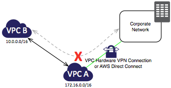
- Edge to edge routing. If VPC A has a peer to VPC B and VPC B has a VPN or Direct Connect connection to a corporate LAN, VPC A cannot use this connection to access resources in the corporate network
- Other scenarios not permitted:-
- A VPN connection or an AWS Direct Connect connection to a corporate network
- An Internet connection through an Internet gateway
- An Internet connection in a private subnet through a NAT device
- A ClassicLink connection to an EC2-Classic instance
- A VPC endpoint to an AWS service; for example, an endpoint to Amazon S3.
- To configure VPC peering:-
- Owner of VPC A sends a peering request to owner of VPC B
- VPC B owner accepts request
- VPC A and VPC B owners add a routing table entry to route traffic to the reciprocal VPC
- Security groups and/or NACLs may need reconfiguring to allow traffic
4.2 Demonstrate ability to design and implement connectivity features of AWS
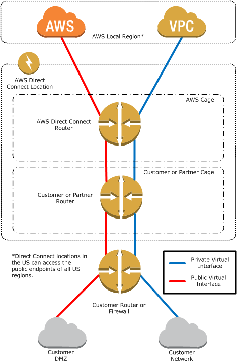
- Direct Connect is a dedicated permanent connection between your premises and AWS. This is brokered via a third parties who are Direct Connect partners
- Supports 802.1q VLANs and you can partition the connection into multiple virtual interfaces, or VIFs
- 1Gbps or 10Gbps connections are available, sub 1Gpbs connections can be bought from Direct Connect partners (AT&T, Colt, Equinix, etc)
- Can help reduce costs when using lots of traffic
- Increase reliability and bandwidth, no longer dependent on internet links
- VPN connection more appropriate for quick setup and modest bandwidth requirements
- Direct Connect uses a public connection when accessing public resources such as EC2 instances and S3 buckets and uses a private connection when accessing resources such as VPC based resources
- Makes AWS a logical extension of your corporate network
- One private VIF connection per VPC (one to one mapping)
- Direct Connect is not inherently fault tolerant, this needs to be built in either by having a secondary Direct Connect or VPN, using BGP to fail over automatically to the backup connection
- VPN has two endpoints, Customer Gateway (CGW) and AWS connection (Virtual Private Gateway or VPG) – these concepts are not used by Direct Connect
- In the US, one Direct Connect connection will grant you access to all regions, traffic stays within the AWS internal network
- Layer 2 network connections not supported
- Prerequisites for Direct Connect include:-
- Your network is co-located with an existing AWS Direct Connect location
- You are working with an AWS Direct Connect partner who is a member of the AWS Partner Network (APN)
- You are working with an independent service provider to connect to AWS Direct Connect.
- Connections to AWS Direct Connect require single mode fiber, 1000BASE-LX (1310nm) for 1 gigabit Ethernet, or 10GBASE-LR (1310nm) for 10 gigabit Ethernet. Auto Negotiation for the port must be disabled. You must support 802.1Q VLANs across these connections
- Your network must support Border Gateway Protocol (BGP) and BGP MD5 authentication. Optionally, you may configure Bidirectional Forwarding Detection (BFD)
- To connect to Amazon Virtual Private Cloud (Amazon VPC), you must first do the following:-
- Provide a private Autonomous System Number (ASN). Amazon allocates a private IP address in the 169.x.x.x range to you
- Create a virtual private gateway and attach it to your VPC
- To connect to public AWS products such as Amazon EC2 and Amazon S3, you need to provide the following:-
- A public ASN that you own (preferred) or a private ASN
- Public IP addresses (/31) (that is, one for each end of the BGP session) for each BGP session. If you do not have public IP addresses to assign to this connection, log on to AWS and then open a ticket with AWS Support.
- The public routes that you will advertise over BGP
- AWS Direct Connect Limits:-
- Virtual interfaces per AWS Direct Connect connection – 50 (soft limit)
- Active AWS Direct Connect connections per region per account – 10 (soft limit)
- Routes per Border Gateway Protocol (BGP) session – 100 (hard limit)
- Sub 1Gbps connections only support a single VIF
- HPC uses Lustre and NFS file protocols, these can often require Jumbo Frames. These are only supported by enhanced networking (10Gbps NIC). Also use Placement Groups to keep instances together for high performance and low latency in a single AZ
- The following instances support enhanced networking:-
- C3
- C4
- D2
- I2
- M4
- R3
- Enhanced Networking is made possible using SR-IOV (single root I/O virtualisation)
- Must be done using HVMs and not PV instances
- A Placement Group is a logical grouping of instances within a single AZ
- Used for low latency connections between instances
- For lowest latency and highest throughput, choose an instance that supports Enhanced Networking
- The latest Amazon Linux HVM AMIs have the module required for enhanced networking installed and have the required attribute set. Therefore, if you launch an Amazon EBS–backed C3, C4, R3, or I2 instance using a current Amazon Linux HVM AMI, enhanced networking is already enabled for your instance
- Older HVMs can be enhanced networking enabled by updating to the latest kernel by running a sudo yum update
- Use the modinfo ixgbevf command to check if enhanced networking has been enabled
- If you lose connectivity while enabling enhanced networking, the ixgbevf module might be incompatible with the kernel. Try installing the version of the ixgbevf module included with the distribution of Linux for your instance
- 1 placement group per AZ, they don’t span AZs
- Placement Groups can span subnets in the same VPC, but they must be in the same AZ
- Existing instances cannot be moved into an AZ
- It’s best practice to size the placement group for the peak load and launch all instances at once
- Try to use the same instance types when creating a placement group
- Elastic Load Balancer (ELB) distributes traffic amongst instances in the multiple AZs
- You can use the operating systems and instance types supported by Amazon EC2. You can configure your EC2 instances to accept traffic only from your load balancer.
- You can configure the load balancer to accept traffic using the following protocols: HTTP, HTTPS (secure HTTP), TCP, and SSL (secure TCP).
- You can configure your load balancer to distribute requests to EC2 instances in multiple Availability Zones, minimizing the risk of overloading one single instance. If an entire Availability Zone goes offline, the load balancer routes traffic to instances in other Availability Zones.
- There is no limit on the number of connections that your load balancer can attempt to make with your EC2 instances. The number of connections scales with the number of concurrent requests that the load balancer receives.
- You can configure the health checks that Elastic Load Balancing uses to monitor the health of the EC2 instances registered with the load balancer so that it can send requests only to the healthy instances.
- You can use end-to-end traffic encryption on those networks that use secure (HTTPS/SSL) connections.
- [EC2-VPC] You can create an Internet-facing load balancer, which takes requests from clients over the Internet and routes them to your EC2 instances, or an internal-facing load balancer, which takes requests from clients in your VPC and routes them to EC2 instances in your private subnets. Load balancers in EC2-Classic are always Internet-facing.
- [EC2-Classic] Load balancers for EC2-Classic support both IPv4 and IPv6 addresses. Load balancers for a VPC do not support IPv6 addresses.
- You can monitor your load balancer using CloudWatch metrics, access logs, and AWS CloudTrail.
- You can associate your Internet-facing load balancer with your domain name. Because the load balancer receives all requests from clients, you don’t need to create and manage public domain names for the EC2 instances to which the load balancer routes traffic. You can point the instance’s domain records at the load balancer instead and scale as needed (either adding or removing capacity) without having to update the records with each scaling activity.
- Elastic Load Balancing supports the processing, storage, and transmission of credit card data by a merchant or service provider, and has been validated as being compliant with Payment Card Industry (PCI) Data Security Standard (DSS)
- For Elastic Load Balancing, you pay for each hour or portion of an hour that the service is running, and you pay for each gigabyte of data that is transferred through your load balancer
- ELB works in conjunction with:-
- EC2
- Auto Scaling
- CloudWatch
- Route 53
- Load balancers can listen on the following ports:
- [EC2-VPC] 1-65535
- [EC2-Classic] 25, 80, 443, 465, 587, 1024-65535
- The HTTP requests and HTTP responses use header fields to send information about HTTP messages. Elastic Load Balancing supports X-Forwarded-For headers. Because load balancers intercept traffic between clients and servers, your server access logs contain only the IP address of the load balancer. To see the IP address of the client, use the X-Forwarded-For request header
- When you use HTTP/HTTPS, you can enable sticky sessions on your load balancer. A sticky session binds a user’s session to a specific back-end instance. This ensures that all requests coming from the user during the session are sent to the same back-end instance
- For each request that a client makes through a load balancer, the load balancer maintains two connections. One connection is with the client and the other connection is to the back-end instance. For each connection, the load balancer manages an idle timeout that is triggered when no data is sent over the connection for a specified time period. After the idle timeout period has elapsed, if no data has been sent or received, the load balancer closes the connection
- By default, Elastic Load Balancing sets the idle timeout to 60 seconds for both connections
- If you use HTTP and HTTPS listeners, we recommend that you enable the keep-alive option for your EC2 instances. You can enable keep-alive in your web server settings or in the kernel settings for your EC2 instances. Keep-alive, when enabled, enables the load balancer to re-use connections to your back-end instance, which reduces the CPU utilization. To ensure that the load balancer is responsible for closing the connections to your back-end instance, make sure that the value you set for the keep-alive time is greater than the idle timeout setting on your load balancer.
- By default, your load balancer distributes incoming requests evenly across its enabled Availability Zones. To ensure that your load balancer distributes incoming requests evenly across all back-end instances, regardless of the Availability Zone that they are in, enable cross-zone load balancing
- To ensure that the load balancer stops sending requests to instances that are de-registering or unhealthy, while keeping the existing connections open, use connection draining. This enables the load balancer to complete in-flight requests made to instances that are de-registering or unhealthy. Default is 300 seconds (1-3600 seconds available)
- Proxy Protocol is an Internet protocol used to carry connection information from the source requesting the connection to the destination for which the connection was requested. Elastic Load Balancing uses Proxy Protocol version 1, which uses a human-readable header format.
- By default, when you use Transmission Control Protocol (TCP) or Secure Sockets Layer (SSL) for both front-end and back-end connections, your load balancer forwards requests to the back-end instances without modifying the request headers. If you enable Proxy Protocol, a human-readable header is added to the request header with connection information such as the source IP address, destination IP address, and port numbers. The header is then sent to the back-end instance as part of the request.
- You can enable Proxy Protocol on ports that use either the SSL and TCP protocols. You can use Proxy Protocol to capture the source IP of your client when you are using a non-HTTP protocol, or when you are using HTTPS and not terminating the SSL connection on your load balancer
- Prerequisites to using Proxy Protocol:-
- Confirm that your load balancer is not behind a proxy server with Proxy Protocol enabled. If Proxy Protocol is enabled on both the proxy server and the load balancer, the load balancer adds another header to the request, which already has a header from the proxy server. Depending on how your back-end instance is configured, this duplication might result in errors.
- Confirm that your back-end instances can process the Proxy Protocol information
- You can’t assign an Elastic IP address to an ELB
- IPv4 and v6 supported on an ELB
- You can load balance a domain apex name, such as bbc.com (no www)
- Enable CLoudTrail on an ELB to output logs to an S3 bucket
- Multiple SSL certificates should mean multiple ELBs unless using a wildcard
- Each load balancer receives a default Domain Name System (DNS) name. This DNS name includes the name of the AWS region in which the load balancer is created. For example, if you create a load balancer named my-loadbalancer in the US West (Oregon) region, your load balancer receives a DNS name such as my-loadbalancer-1234567890.us-west-2.elb.amazonaws.com
- Use a friendly DNS name for your load balancer, such as http://www.example.com, instead of the default DNS name, you can create a custom domain name and associate it with the DNS name for your load balancer
- To improve the performance of your NAT instance, you can:-
- Scale up (choose a bigger instance)
- Enable Enhanced Networking
- Scale out (add more instances)
- Create a new NAT instance and new subnet and route new subnet traffic through it. Subnets and NAT instances are associated on a one to one basis
- HA for NAT is also possible, but remember it’s an active/passive configuration

Pingback: AWS SA Prof 공부 (Domain 4) | Kyupok's AWS Study 블로그